Measurement Setup
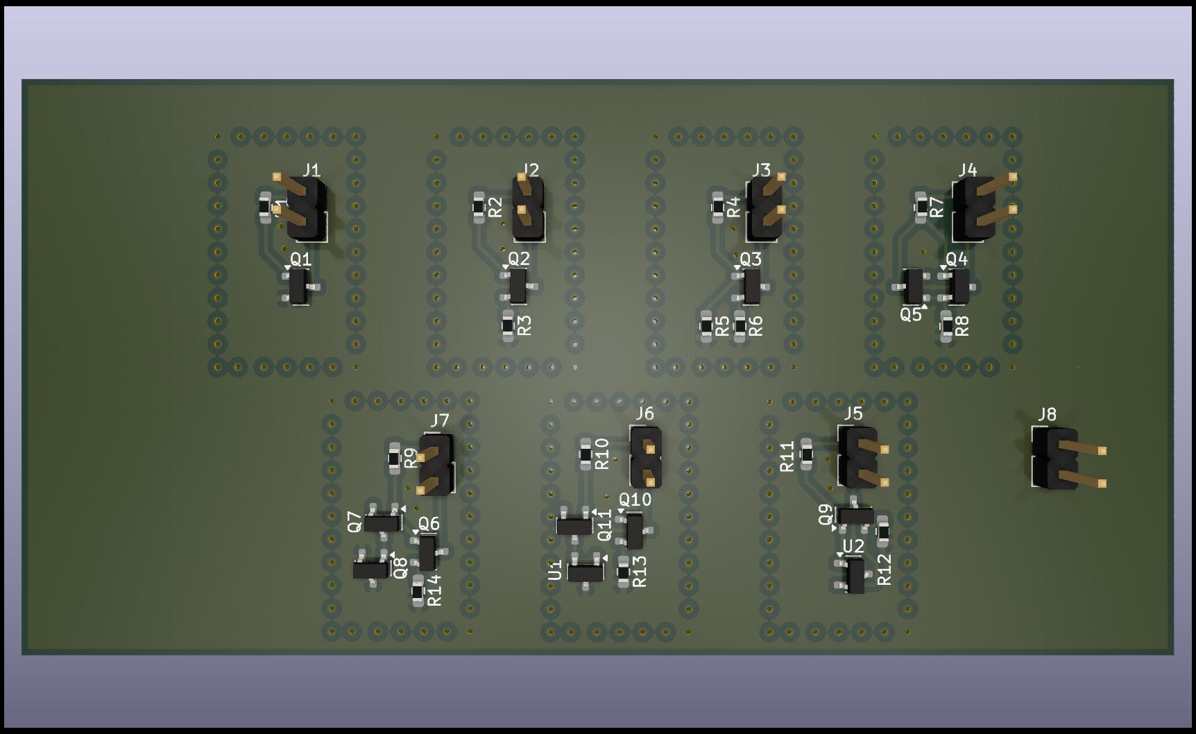
The measurement circuit was implemented on a dedicated PCB containing all simulated current sources.To enhance thermal isolation, each source was surrounded by vias, thereby reducing heat transfer between neighboring circuits.
Furthermore, all components were sourced from the same manufacturing batch to ensure optimal parameter matching.
A schematic representation of the circuit is provided on the right.
The experimental setup employed a temperature-controlled heat plate in combination with a thermal insulation layer placed above the PCB.
To suppress self-heating effects, the initial bias current of each source was intentionally kept low.
For each temperature point, measurements were conducted for a minimum duration of 30to40 minutes, or until complete stabilization of the thermal gradient was achieved.
The current measurements were performed using an HP3457 multimeter connected via GPIB. It should be noted that the instrument had not been recently calibrated; therefore, the reported values may include a systematic offset and should be interpreted with appropriate caution. As the supply source, a stable and filtered 12 V power supply was employed to minimize noise and voltage fluctuations. Both the PCB design files and the corresponding measurement data are available on GitHub.