Since I often need to perform tasks such as removing paint and de-rusting metal parts, I always wanted to have a
sandblasting system. However, my original compressor could not meet the challenge of delivering the large,
continuous airflow required. As I already owned three smaller compressors, the idea was born to combine them into
one system.
To achieve this, I designed a control circuit using a small Siemens Logo! PLC, which manages the entire setup.
A simplified schematic (pseudo R&I) is shown on the right.
On the right side of the schematic, the three compressors are connected in parallel using solid copper piping.
The pipe angles are deliberately designed to guide any condensation water in the correct direction.
At the bottom, a pressure relief valve is installed to ease compressor startup and simultaneously discharge any water buildup during the process.
A check valve ensures that the air tanks are not drained in this step.
Following the check valve, the compressed air passes through a Liebig condenser, which reduces the temperature of the incoming high-pressure air.
The main air tanks are lightweight aluminum truck tanks, chosen specifically because they are corrosion-resistant.
Each tank is equipped with its own overpressure relief valve and a shared drain line for removing condensed water.
Additionally, the downstream pressure lines include an integrated water separator, which is also connected to the common drain line.
This drain line is operated by a small electromagnetic valve to automate the release of accumulated water.
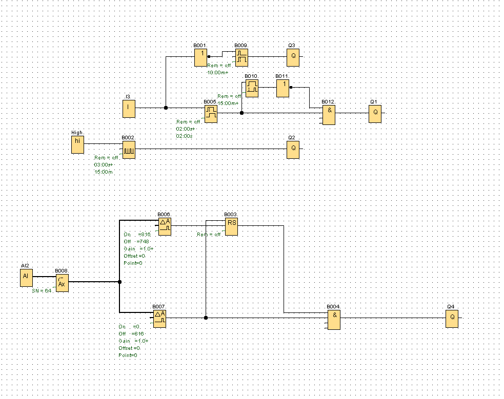
The PLC application is illustrated on the right and is divided into three functional sections:
- Fan Control The upper section implements fan control. The fans are activated whenever one or more compressors are running. To ensure adequate cooling, the fans remain active for an additional 15 minutes after compressor shutdown.
- Pressure Relief Valve Control The second logic path, triggered by input I3, controls the pressure relief valve. The valve opens whenever input I3 is inactive, and remains open for two seconds after activation. This sequence supports both safe startup and pressure equalization.
- Water Drain Control The middle logic path handles the automatic discharge of condensed water. The drain valve is activated periodically every 15 minutes to remove accumulated moisture from the system.
- Pressure Monitoring and Safety Shutdown The bottom section is responsible for monitoring line pressure. A window comparator function is implemented to controll the pressure levels. If the measured pressure exceeds the defined threshold, the compressors are shut down to prevent overpressure conditions. They are turned on again if the lower threshold is reached.